WEST SYSTEM: Building ‘Lockdown’ – Working with Swallow Yachts
I’ve been involved in sailing since my mid-teens, albeit more sporadically than consistently. Throughout this period, I primarily served as a crew member on various skippers’ boats, gaining a wealth of nautical experience. My most recent nautical adventures were based out of Oban on the west coast. It was during one of these journeys that I observed a flotilla of Drascombes cruising in the Minches, and that planted the seed of an idea. In 2010, I retired and boarded on the search for a suitable project boat. Despite examining several options, none quite matched my specifications. That’s when I came across Swallow Yachts (formerly Swallow Boats) and became enamoured with a Bay Cruiser 23.
Given my inclination for crafting and mending items, coupled with my hands-on approach in renovating our family home from the 1900s, I realised I could channel these skills and the tools I’ve accumulated into refurbishing a Crabber. The ultimate goal? To sail it around Britain once I decide to retire.
A few years had past. Within this time, I established a connection with Matt Newland, the owner and designer of Swallow Yachts.
The Idea of Constructing a Scaled-Down Swallow Yachts Raider
I had decided it was time to part with the Bay Cruiser. However, my passion for nautical projects persisted, and after a year without sailing, I yearned to be back on the water. I had a specific idea in mind: to construct a scaled-down version of one of the open boats Swallows was known for—the Raiders.
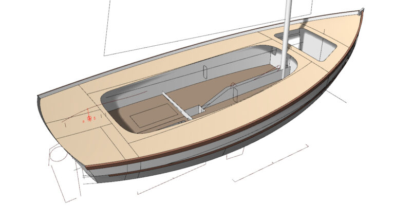
During the Swallow Raid in 2020, I was taking shelter in a bar due to inclement weather. This is when I discussed an idea with Matt. Acknowledging potential stability challenges with a smaller craft, he confidently affirmed his ability to design one meeting my specifications. I emphasised the need for a lightweight, water-ballasted boat with a simple rig, minimal halyards, and control lines, underlining the importance of construction simplicity. I have always found the “stitch and glue” technique with plywood intriguing. The following morning, Matt presented a preliminary design he had crafted on his laptop.
Finalising the Design and Modifying the Boat
As the Southampton Boat Show approached, our discussions had resulted in the finalisation of Matt’s design. While at the show, both of us noticed the Epropulsion “pod” and collectively decided to modify the stern of the boat to integrate it within a well, opting for this over the conventional outboard. The specific details regarding how the pod would be raised and lowered, or if it would be at all, were left to my discretion. Matt generously offered to craft the components in a 1 inch to the foot scale (or 1 in 12 for those using metric measurements), using 1mm thick ply.
Indeed, a week later, an A4 envelope arrived, housing all the components. The CAD system had transformed the 3D “model” into a series of flat pieces, precision-cut by his computer-controlled cutter. Over the weekend, I thoroughly enjoyed the process of figuring out their assembly, occasionally finding myself inadvertently bonding both the pieces and my fingers together with superglue (and accelerator).
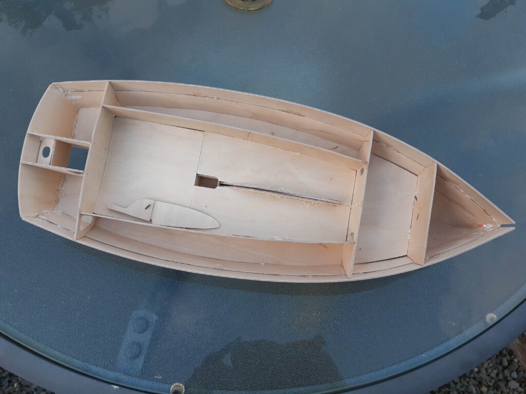
Decision to Proceed with the Project
After thorough consultation, I made the decision to proceed with the project. Matt provided a formal quotation for the supply of pre-cut pieces in 6mm ply, recommending the use of WEST SYSTEM Epoxy products for adhesives and fillers as necessary. Moreover, he extended the option of including a dedicated boat trailer to serve as the build platform. The entire set of components was scheduled to be available for delivery within a six-week timeframe.
The current challenge revolved around acquiring a deeper understanding of the “stitch and glue” technique and identifying a suitable location for the boat construction. In my research, informative videos on YouTube proved invaluable. Opting for plastic cable ties instead of steel wire for the stitches was a practical choice. The intention was to remove them once the glue had set.
Finding a Suitable Location for Boat Construction
Although initially contemplating building the boat in the garage, its integration with the house and limited space led me to reconsider. Anticipating potential dust-related domestic issues, I explored alternative options. Fortunately, a local farmer offered the use of a somewhat dilapidated and considerably dirty cowshed for a six-month rental period. Determined to make it work, I undertook the task of cleaning, repairing the sliding door, and establishing a functional workspace. I ensured all-around protection with cost-effective tarpaulins. Additionally, I secured a second-hand woodburning stove, chimney, and an apparently endless supply of broken pallets to maintain a reasonably warm environment.
Swallow Yachts Flat Pack
In November 2019, six weeks after making the arrangements, I retrieved a heat-shrink-wrapped “flat pack” from the Swallow Yachts yard in Gwbert. The pack comprised 13 sheets of 6mm plywood, along with 25kg of WEST SYSTEM 105 Epoxy Resin, cans of WEST SYSTEM 205 Fast Hardener and WEST SYSTEM 206 Slow Hardener, a substantial tub of WEST SYSTEM 406 Colloidal Silica, and another tub of WEST SYSTEM 410 Microlight Filler. The entirety of this strictly packaged material was loaded onto the boat trailer for transport.
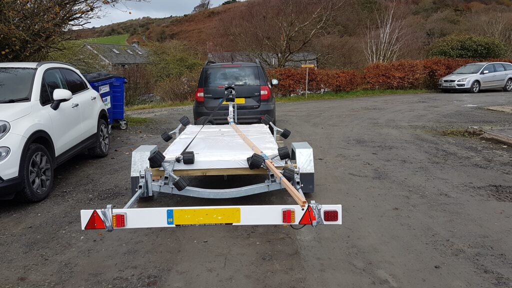
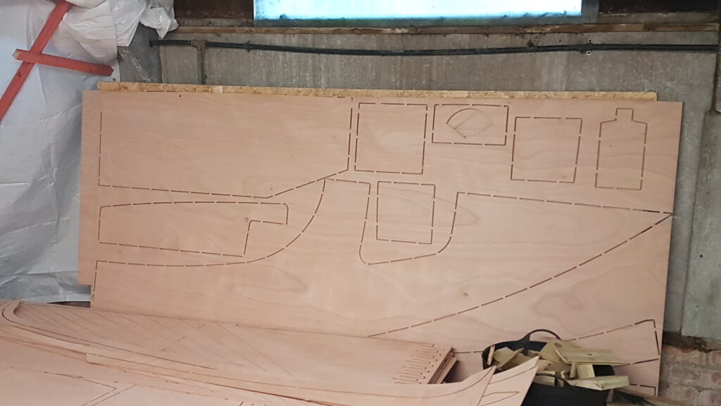
On the subsequent day, in the tidy space I set up inside the “cowshed,” I took a closer look at my purchases. I noticed the outlines of the different plywood parts partially cut from the sheets, thanks to the clever CAD system. The system had strategically arranged the parts to minimise material wastage. The task at hand involved precisely cutting the small “tabs” that held the sheets together, providing access to all the required components.
The Assembly Process
This operation resembled the careful and precise assembly involved in putting together a typical plastic model kit! The hull construction used three pairs of “planks.” The bottom pair, broad in the middle and tapering towards the bow, were stitched along the edges to form a distinct boat shape. The second plank aligned precisely with the bottom planks. The third plank featured a cut groove about 10mm above the bottom edge, sitting atop the second plank, enhancing the overall hull structure.
Designing The Hull Structure
Transverse bulkheads were designated as formers to shape the hull section. Due to the boat’s length surpassing the original plywood sheets, each plank was to be crafted from front and back segments, interconnected by pre-cut “fingers.” The cockpit floor comprised three distinct parts – two mirrored components flanking the centreboard case and a third spanning the aft cockpit, functioning as a cover for a buoyancy tank. Additional buoyancy tanks were strategically placed each side of the cockpit, between it and the boat sides, , at the bow, and on both quarters.
Preparing for the Build Phase
Elevating the trailer onto bricks, I double-checked the level of the main frame, ensuring precision both lengthwise and across its width. Employing two transverse bulkheads as guides, I crafted a pair of formers, marking the boat’s centre line on them. Securely fixing these formers across the trailer at the appropriate longitudinal spacing, I established stable supports for the hull during construction. With these preparations in place, I seamlessly transitioned into the build phase. Before assembling the hull, there were preliminary tasks to complete, and I could tackle these in the relative warmth of my home garage. Specifically, the fore and aft sections of the planks required gluing together. Without much consideration, I began to “fettle” the finger joints, ensuring they fit snugly before proceeding to bond them together.
Constructing and Installing Rudder and Centreboard
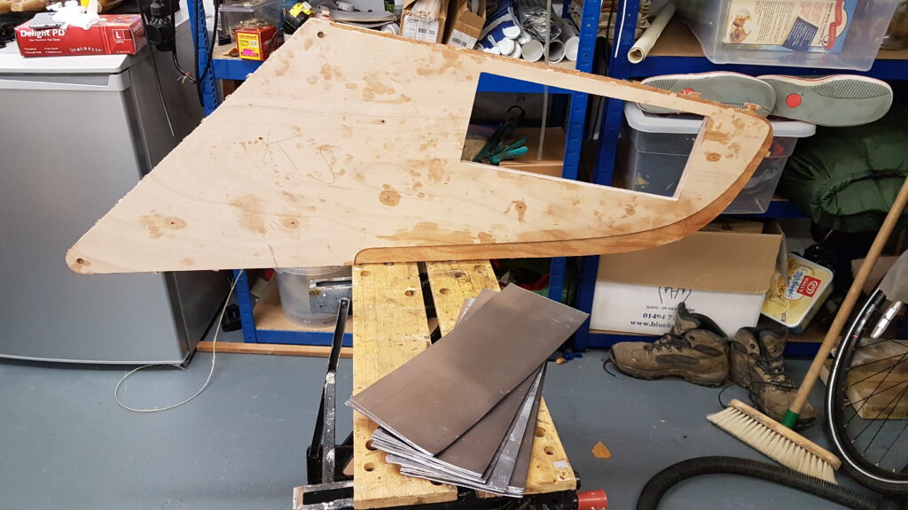
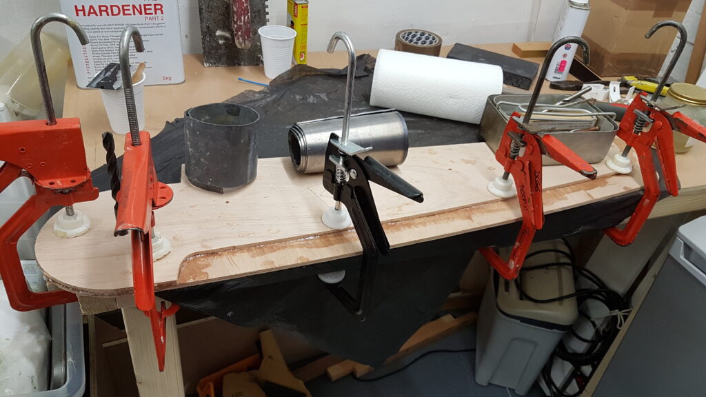
The construction of the centreboard case allowed for assembly as an open box before integrating it into the hull. Crafting both the rudder and centreboard involved laminating plywood—5 layers for the former and 3 for the latter. Given the essential need for these components to remain flat, I secured them to a 20mm plywood “surface plate” using clamps during the lamination bonding process. To prevent undesired adhesion of the laminations to the plywood sheet, I strategically employed a sizable polythene rubbish basket as a protective barrier.
I incorporated small drilled holes at intervals through the laminations. These holes served the purpose of allowing me to monitor the epoxy flow between the laminations as they were clamped together. Commencing with the rudder, which proved successful, I proceeded to the centreboard. The inner laminations of the centreboard had a rectangular hole cut near the tip, designed to accommodate lead sheets. This strategic addition served to bias the board down when installed in the boat.
Step-by-Step Process of Boat Hull Construction and Troubleshooting
I attached the three inner laminations and carefully cut roofing lead sheets to fit the designated opening. To figure out the required amount, I consulted the designer, who simply said, ‘Until the hole is full.‘ This advice led to the use of exactly 12.5 kg of lead. Afterward, I assembled one outer layer with the inner laminations and lead sheet on the “surface plate.” The gaps between the lead sheet layers were filled with WEST SYSTEM Epoxy, and the entire structure was securely sealed in place with the outer skin. With these components ready, the next step was to return to the cowshed for hull construction.
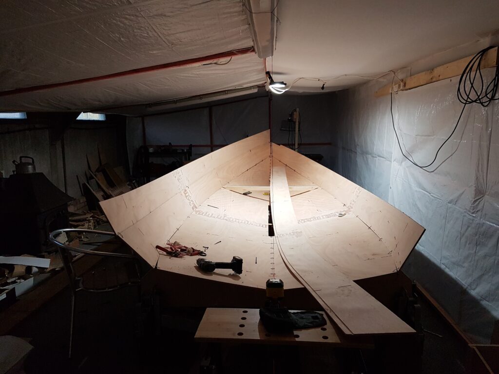
Anticipating the need for a trial assembly before applying adhesive, I drilled holes, positioned the planks, and secured them in place with cable ties. However, upon installing the third plank and the midships transverse bulkhead, a discernible issue emerged. Despite my efforts to tighten the cable ties, the bow exhibited an ominous twist to port (bearing in mind the evolving boat’s perspective). In an attempt to rectify the situation, I experimented with the placement of a couple of cross bulkheads, but regrettably, the issue persisted.
Overcoming Challenges in Boat Alignment
As I took a closer look at my progress, it dawned on me that the bottom pair of planks were off by 2mm in their fore-and-aft alignment. This discrepancy had a cascading effect, disrupting the entire configuration. To address the issue, I had to cut all the cable ties and start afresh. Realising the importance of precise measurements for alignment, I considered using a spirit level to ensure consistent height on each side of a bulkhead. However, I pondered over how to guarantee alignment along the entire length of the boat.
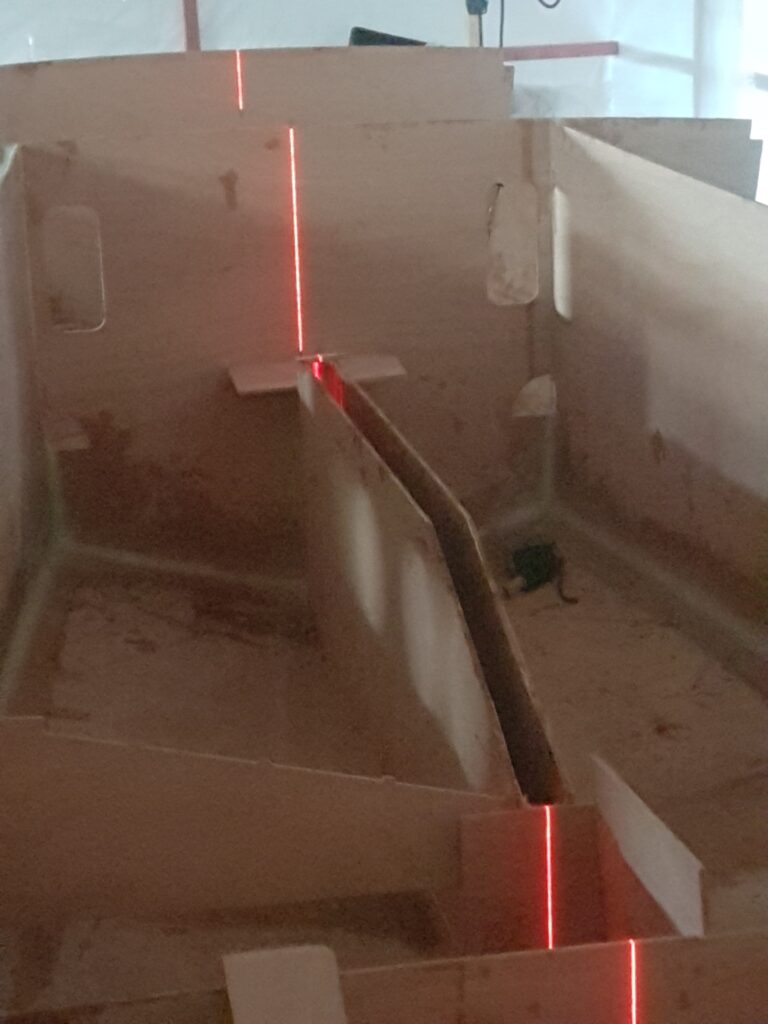
I opted for a straightforward approach by suspending a string along the shed ceiling, ensuring its alignment with the longitudinal join of the bottom planks using plumb bobs. Subsequently, I attached additional plumb bobs along its length to monitor the position of the bulkheads. However, this turned out to be less effective, as they swayed with even the slightest breeze. Recognising the need for a more reliable solution, I conceded and turned to online shopping. Before long, I was “clicking and collecting” a laser level—a simple yet effective tool that left me wondering why I hadn’t considered it earlier.
Aligning Planks and Shaping the Bow
Having carefully aligned the bottom pair of planks, I positioned all the transverse bulkheads. Using cut lengths of wood, I ensured their parallel orientation, taking advantage of notches cut by the NC machine for precise alignment.
After a productive morning’s work, with everything securely held in place by cable ties, the assembly looked promising. I began the process of “tacking” glue on these parts, using super glue and accelerator in small 10 mm patches at 350 mm intervals along the joins. This method resulted in a sturdy and well-aligned structure, with the cable ties remaining in place for the time being. As I proceeded to add the second plank, fixed and tacked in a similar manner, a new challenge surfaced.
Solutions to Plywood Bending
The second plank required a smooth yet sharp bend around two bulkheads to shape the bow. Despite attempts to facilitate the process with warm water-soaked plywood, an unwelcome sharp crack disrupted the attempt to shape the starboard plank, giving it an obvious kink. Determined to address this setback, I explored a method to encourage the plank to conform to a smooth curve and maintain its shape.
I chose to gently shape it into a smooth curve using a batten placed outside the hull, complemented by a few wood clamps to secure it to the plank. By bending both the plank and the batten into the desired smooth curve, I applied epoxy and glass fibre cloth to the inside of the plank, allowing it to set. The outcome was successful—upon releasing the batten, the plank retained the desired smooth curve. Approaching the fitting of the port plank, I exercised heightened care, successfully navigating the process without encountering the dreaded crack.
Securing The Initial Planks and Preparing for the Third
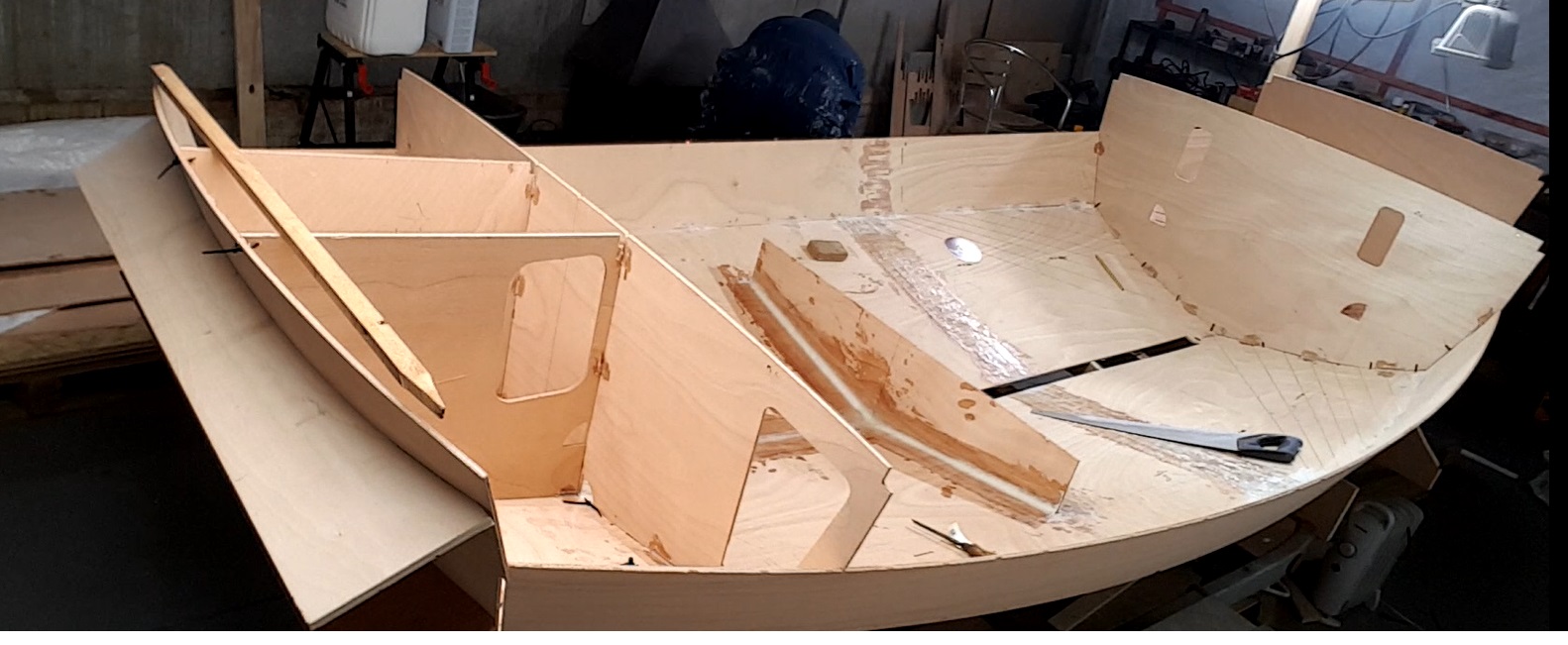
I had successfully secured the initial two planks into position. As I prepared to incorporate the third plank, it dawned on me that doing so would hinder my access to install both the cockpit floor and the centreboard case within the hull. Consequently, I temporarily set aside the third plank. Growing more assured in the overall framework, I upgraded the fasteners from superglue tacks to slightly larger epoxy ones, while retaining the cable ties for stability.
I proceed to affix the cockpit sides and construct the “motor compartment” at the stern. Upon finishing these components, I concluded that it was opportune to explore the method of filleting the joints and subsequently fortifying them with glass fibre tape. This proved to be a somewhat messy! As January 2020 drew to a close, I had effectively addressed all the joints I had previously fashioned, prompting me to indulge in a holiday under the sun.
Resuming the Project Amidst the Lockdown
I resumed my project just before the onset of the Covid pandemic and subsequent lockdown. Contemplating whether to stay at home or not, I considered the isolated nature of the cowshed, with no colleagues working alongside me or any immediate proximity to other farm buildings. This led me to the conclusion that I wouldn’t pose a risk to myself or others if I continued with the construction. Establishing a routine, I began my day by cycling to the cowshed (a 3-mile journey each way, providing beneficial exercise). Upon arrival, I would light the wood burner, set the kettle on, and tidy up the remnants from the previous day, including addressing any mice that had invaded overnight. Using the chainsaw, I would then cut the required fuel for the day before a final sweep to maintain cleanliness.
Installing the Centreboard Case and Constructing the Bilge Area
I installed the centreboard case, adding a small spacer panel ahead of it. Following this, I constructed the bilge area—a compact square tank just aft of the centreboard case. For supporting the cockpit floor, I attached scantlings (25mm square lengths of larch). The challenge lay in fitting these scantlings to both the flat sides of the centreboard case and the curved sides of the cockpit. Given the impracticality of clamping them in place during the epoxy setting process and my aversion to using screws, I turned to 1mm ply remnants from my modelling days. I carefully cut 10mm square pads from this material and used superglue to secure them to the scantlings at a 300mm pitch.
After securing these components in place, I carefully positioned the scantlings on the cockpit and centreboard case sides to mark the locations for the pads. Following the preparation of epoxy, I applied it along the scantlings, ensuring it stayed clear of the pads. Simultaneously, I coated the pads with superglue and sprayed accelerator on the designated spots. This allowed me to align the scantlings accurately, holding them in position until the superglue took hold. I could then leave them undisturbed while the epoxy underwent the curing process.
Success! This method encouraged me to employ it multiple times throughout the later stages of the construction.
Installation of the Cockpit Floor and Addressing Potential Discrepancies
The next tasks involve the installation of the cockpit floor, which is comprised of three plywood pieces. Two of these are placed on either side of the centreboard case, featuring a cut-out around the bilge to shape the upper section of the water ballast tanks. The third piece spans across the rear of the cockpit, covering the designated buoyancy tank area. Before securing these elements in place, it was necessary to apply an epoxy coating to the insides of the tanks and enhance the plank joins with fiberglass tape.
Addressing Potential Discrepancies
While undertaking this job, I identified a potential discrepancy: the underside of the cockpit sole aligned with the tops of the ballast tanks, whereas the waterline was intended to be a few inches below the cockpit sole to avoid constant dampness. This raised concerns about the formation of an undesirable water bubble at the top of the ballast tanks. Fortunately, I discovered surplus Celotex insulation material at a builder’s yard, measuring approximately 75mm in thickness—a suitable solution for the issue at hand. I accurately tailored the material to fit beneath the sole plate and affixed it securely in place through adhesive bonding.
Installation of the Cockpit Sole
With the insulation in place, I proceeded to adhere all three components of the cockpit sole. It’s worth noting that I had previously drilled holes on the side of the bilge well and installed drain plugs with screw-in bungs. This design allowed for the flooding and draining of the ballast tanks through the well, contingent on the availability of a suitable pump and holes in the bottom of the bilge. These additional features, including the fitting of drain plugs with bungs, were implemented at a later stage. While attending to these modifications, I took the opportunity to apply an epoxy coating to the interior of the bilge for added protection.
Shifting Attention to the Botas Underside
I proceeded to install the scantlings along the inside of the third plank, creating a support structure for the deck. The standard procedure involved the use of cable ties, initial tacking, and the application of epoxy coating, reinforced by the addition of glass fibre tape along the seams. The fitting of the transom was done carefully, aided by a former which was thoughtfully provided by Matt, maintaining a uniform curve while the epoxy hardened. I replicated this process to finalise the construction of the “engine bay.”
It was time to shift attention to the boat’s underside, and I enlisted the help of two friends, maintaining a safe distance as per social distancing guidelines. Together, we carefully lifted her off the trailer and gently lowered the inverted hull onto a pair of builders’ planks spanning the trailer. Notably, the thin ply of the centreboard case protruded about 40 mm from the hull and required protective measures.
Protective Measures for the Centreboard Case
For this purpose, I had acquired some 50 x 20 Iroko and crafted two strips to flank either side of the case. Additionally, I cut a couple of V-shaped pieces to be positioned both ahead and astern of it, ensuring comprehensive protection for the extended section of the centreboard case.
Given a subtle fore and aft curve in the hull at this juncture, I had to flex the strips as they were epoxied into position. Employing a practical method, I used a rope threaded through the centreboard slot, along with a pair of sturdy battens. By twisting the rope, I managed to pull the strips downward at each end of the slot, effectively accommodating the curvature. This approach proved to be quite effective.
Joining the Centreboard Case to the Prow
Furthermore, Matt had provided a couple of lengths of Iroko, pre-machined to conform to the shape of the prow. My next task involved seamlessly joining the centreboard case to these pre-shaped pieces.
The curvature in the hull persisted from the centreboard case to these sections. Despite attempting to mould my Iroko piece to conform to the hull, even after steaming it for a couple of hours using a wallpaper stripper boiler and insulated plastic pipe, I found it resistant to bending. Consequently, I opted to cut the Iroko into horizontal strips and then laminate them into place.
Streamlining the Process with a Makeshift Bench Saw
To streamline this process, I constructed a casing around my old Black and Decker hand circular saw, secured it to my workmate, and transformed it into a makeshift (albeit very unsafe—please avoid attempting this at home) bench saw for cutting the laminations. Following these preparations, I effortlessly epoxied the laminations into place without encountering any issues.
Covering the bottom with glass fibre cloth turned out to be a more straightforward task than I had initially expected. After cutting the cloth to a rough shape for one side, I used masking tape to secure it approximately in position. Then, a mixture of epoxy, without filler and with the use of fast hardener, was poured onto the cloth. Employing a squeegee, I skilfully spread the epoxy across the cloth, and to my satisfaction, the glass cloth effectively held the epoxy with no runs.
Commencing the Hull Fairing Process
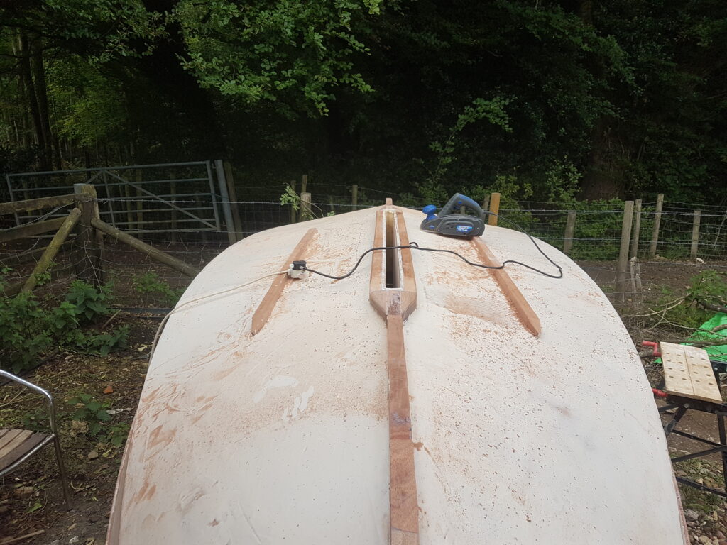
It felt like the right moment to commence the hull fairing process. With a stretch of dry weather in the forecast, I moved the boat and trailer outdoors. First on the agenda was removing the multitude of cable ties that adorned the hull. Successively, I began the thorough task of rubbing it down with fine wet and dry sandpaper, preparing it for a coating of epoxy mixed with WEST SYSTEM 410 Microlight Filler. For the initial stages of this process, I utilised an orbital sander connected to my “wet and dry” vacuum, effectively managing the dust. However, due to the noise level, I had to don ear defenders and a mask for protection.
Experimenting with Epoxy, Hardener, and Filler
I engaged in a series of experiments to achieve the optimal combination of epoxy, fast-cure hardener, and filler, ensuring it did not excessively flow before setting. During the final fairing process, I encountered a challenge with the orbital sander, as its suitability for the tight curves of the hull at the bow was limited. To address this, I innovatively devised a flexible hand sander, ensuring a seamless blend along the curves. Additionally, I incorporated a pair of Iroko strips onto the hull, functioning as “bilge keels” for stability when the vessel is beached.
Returning to the workshop, with the hull reinstated in the upright position, the next step involved crafting the samson post and securely affixing it to the forward bulkhead. Subsequently, the task was to install the deck, which was provided in four distinct segments. These parts feature butt joints along the centreline at both the bow and stern, as well as the midpoint along the length. This design ensures a balanced and symmetrical structure for the boat.
I joined the front and rear portions of each side using epoxy before affixing the deck components to the boat. To strengthen this connection, I applied glass tape to both the upper and lower surfaces. After this, I epoxy-bonded the port and starboard half decks to the hull and used short stainless screws to draw the deck down onto the scantlings. This method ensures a secure and durable construction.
Trimming the Deck Perimeters and Addressing Longevity Issues
Following the complete curing of the epoxy, I trimmed the deck perimeters that had extended slightly beyond the upper surface of the top plank. In instances where the deck joint lacked sufficient support, I employed offcuts of plywood on the underside to establish an overlapping joint, securely fastened with screws.
Post-epoxy setting, the extraction of screws proved to be a straightforward process. My apprehensions revolved around the potential longevity issues, prompting the removal of screws to avert future complications in the boat’s lifespan. Now, with the hull complete, the focus shifted to the addition of finer details – an aspect that has not traditionally been my forte. This involved incorporating an Iroko top rail, coamings for both the cockpit and the sizable fore hatch, the latter requiring a matching hatch cover. Furthermore, I aimed to repurpose two of the smaller midships buoyancy tanks into watertight lockers. Additionally, a critical oversight almost slipped my mind: the necessity for a designated box to house the mast’s foot and a deck fitting to furnish requisite lateral and longitudinal support.
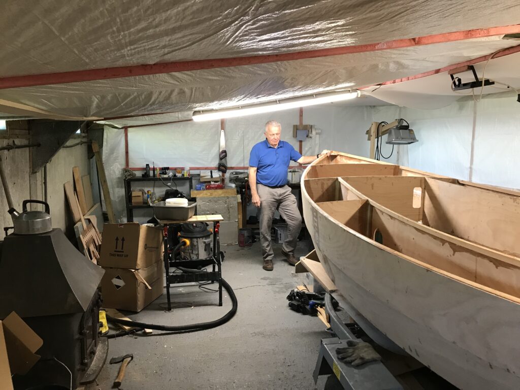
Positioning the Box and Deck Fitting
The said box found its place on the cockpit floor, situated just ahead of the centreboard case. Meanwhile, the deck fitting materialised in the form of two sections of 25mm Iroko, fashioned into the semblance of a garden fork handle and securely fastened to the deck immediately forward of the mast step box.
I intended to craft the uppermost rail from 60 x 15mm Iroko. However, I didn’t have any pieces on hand that were long enough to make a side out of one piece. This required me to adjust my plans accordingly. Consequently, I opted to join two planks on each side, employing a scarfed joint for the connection. Recognising the intricacy of this task, I steered clear of a freehand approach and made a specialised scarf joint box, similar to a mitre box but featuring a shallower angle. This proved to be highly effective, with the port and starboard top rails cut and epoxied into position.
Overcoming Challenges with the Taffrail Installation
However, the installation of the taffrail presented a distinct challenge. Despite the counter’s design facilitating the use of a straight piece of wood bent to form the circular line of the taffrail, bending the entire Iroko section proved impractical. Consequently, I opted to cut the Iroko into 60 x 3 mm strips and then laminated them onto the counter. The creation of the Iroko cockpit coaming demanded additional lamination, necessitating inventive clamping methods to secure the laminations in place during the epoxy curing process.
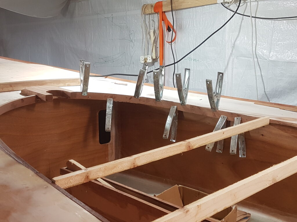
I had reached an agreement with Swallow Yachts regarding the painting of the hull. As the scheduled time for the application was rapidly approaching, necessary preparations were diligently underway. I carefully faired the deck and seamlessly fitted the centreboard. Securely attaching the rudder to the stock and suspended it on the pintles. I lifted the boat off the trailer to fit the rollers and supports. With the concerted efforts of our four-person team and the strategic use of straps, we smoothly elevated the boat back onto the trailer. Now, the boat is ready to go. This process ensures that the boat is secure and prepared for its next journey.
Journey to Swallow Yachts Spray Booth
During the ongoing lockdown, the M4 west from London presented a pleasantly deserted scene. The typically bustling motorway was devoid of any visible presence, including law enforcement personnel. Anyway, my story was that I was on my way to a business appointment. When the vessel arrived, it was delivered to the newly established spray booth at Swallow Yachts. This is typically the next step in the process where the vessel will undergo final finishing touches. In its current state, the boat appeared somewhat akin to an unpolished gem, with various coloured patches adorning its exterior. Despite its initial unassuming appearance, the boat held the promise of transformation under the expert hands of the Swallow Yachts team.
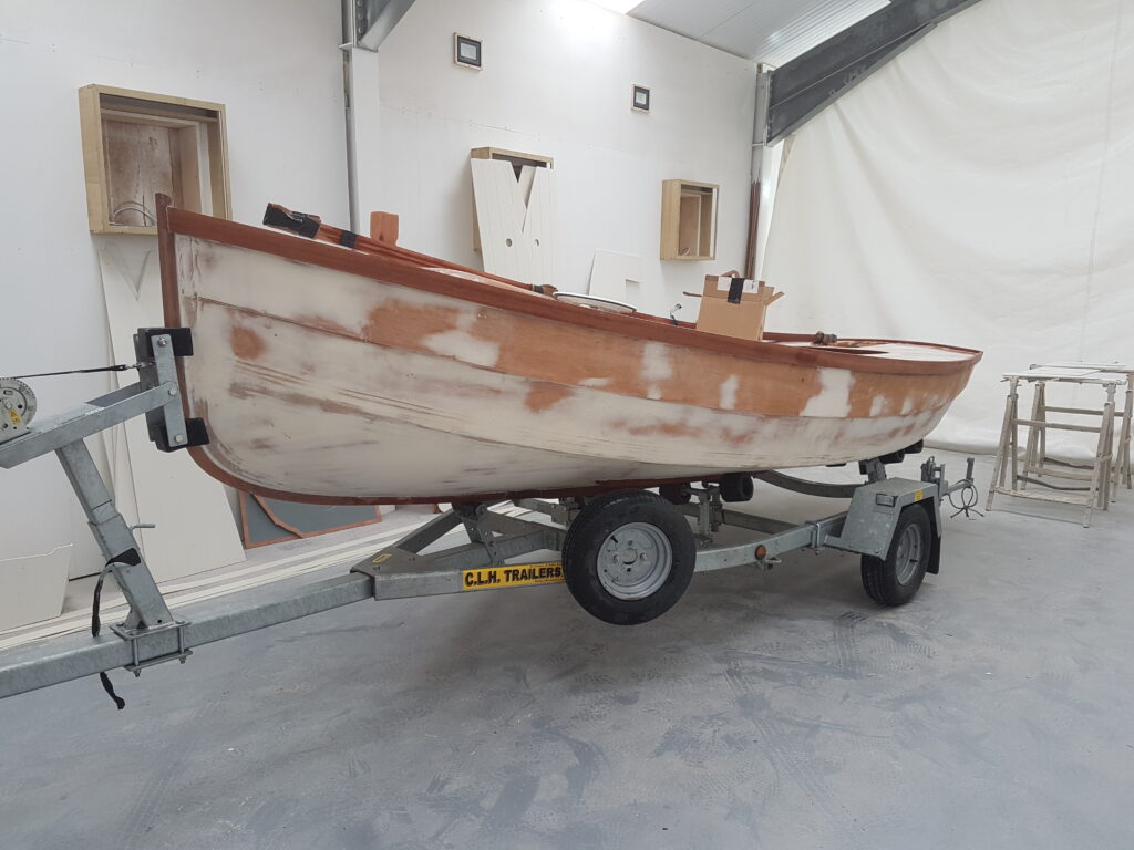
After a four-week period, a significant transformation had taken place. Now, the next phase involved the fitting out of the vessel with all the essential boating equipment. This included a carbon fibre mast, a wooden boom, and a carbon yard. A Hyde sail equipped with reefing points was carefully incorporated into the setup, along with the necessary halliard and sheets.
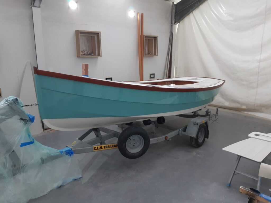
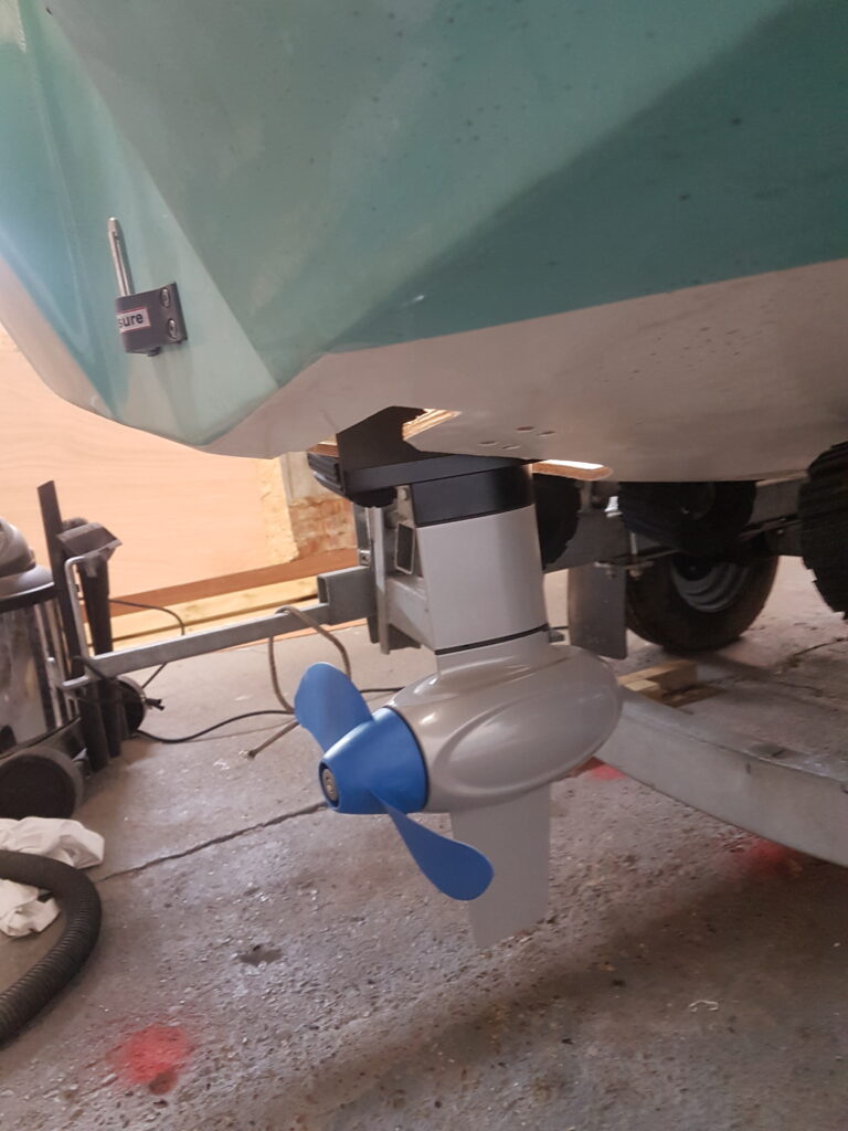
Other essential additions comprised a tiller, several fenders, mooring ropes, and a well needed anchor. Notably, a strategic modification was made to the engine compartment by cutting a hole in the bottom. This modification enabled the installation of the E propulsion pod, which was suspended on a wooden platform capable of sliding up and down on a pair of stainless-steel tubes. This unusual design allowed the propulsion pod to be lowered into the water, enabling the boat to navigate with efficiency and precision.
Crafting a Dedicated Mount and Waterproof Compartment
A dedicated mount was crafted at the aft end of the cockpit floor to securely house the battery. Additionally, a waterproof compartment for electrical connections was ingeniously fashioned using a sandwich box. Once these arrangements were in place, the battery underwent a thorough charging process, and the motor underwent rigorous testing to ensure optimal performance.
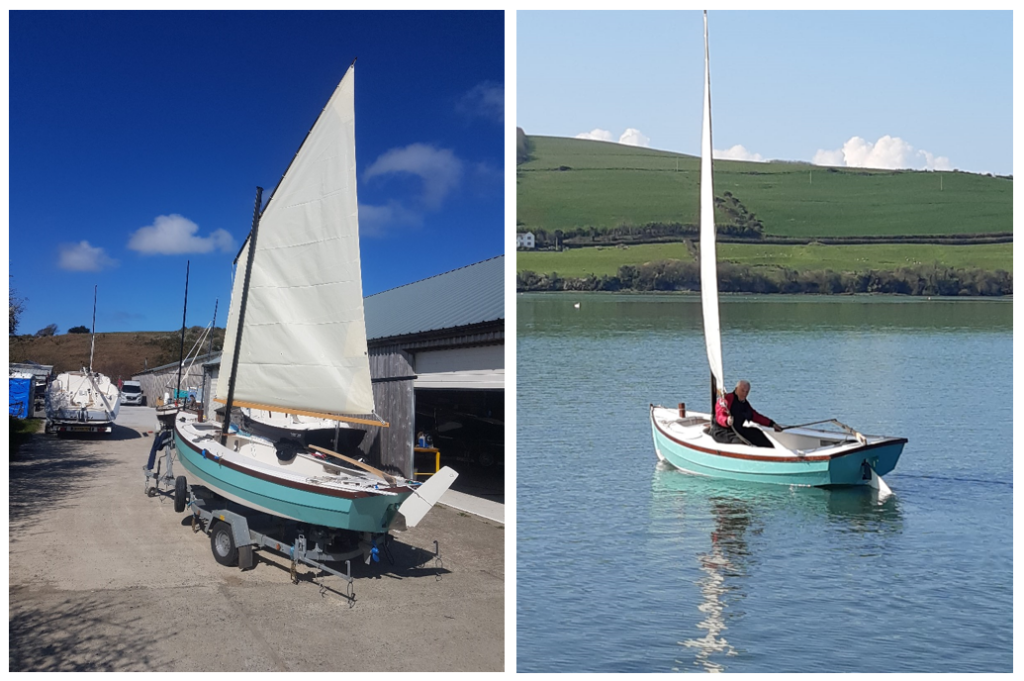
On a serene and sunlit morning, the nautical vessel “Lockdown” was gracefully launched off the slip at the yard. However, in an unexpected turn, the water level receded rapidly, leading to a grounding incident. Despite this initial hiccup, the vessel now proudly bore the name “Lockdown,” marking a significant milestone in its journey to becoming seaworthy.
Ever since, they have stationed her aboard the trailer at Northney in Chichester Harbour, and on a couple of occasions, they have hauled her to Cornwall. They have made various enhancements – they have reduced the aperture in the centreboard case to minimise water splashing up. I’ve added additional lines to enhance manoeuvrability during sail lowering, tweaked the mast’s angle, and adjusted the halyard’s placement on the yard.
Current Performance and Issues
Presently, she exhibits a slight weather helm, showcasing impressive downwind performance, and emits a melodic hum when surpassing 4 knots (a rarity!). On favourable days, she smoothly tacks through approximately 120 degrees. However, there are occasional issues with the centreboard sticking. The tubes supporting the motor have been exchanged with stainless steel rods, and I encountered a mishap when towing her under some trees with the mast raised – it ended up breaking. Now, the lower three feet of the mast have been fortified with a solid ash piece. Up to this point, I haven’t ventured out in winds exceeding F4.
Reflections on the Construction Process
Reflecting on it, I’ve lost track of the actual hours invested in constructing her.I gave up any attempt at estimation around the 400-hour mark, and by the end, it likely neared 550 hours (though, to tell the truth, the construction process never truly ends once they build a boat, as there’s always room for improvement). Without the impetus of the Covid lockdown, I’m uncertain whether I would have completed her.
Given the circumstances, the project couldn’t have arrived at a more opportune moment, offering me a sense of purpose with challenges to navigate during a challenging period. It proved beneficial for both my wife and me, pulling me out of the house and providing us with a daily topic of conversation. Would I undertake another build? Most likely not! They have torn down the cowshed and replaced it with upscale industrial units, which has made the rents currently unaffordable for me.
Have you subscribed to our FREE monthly newsletter? Sign up here!
Working on a project? Share it with us! Click here…

